
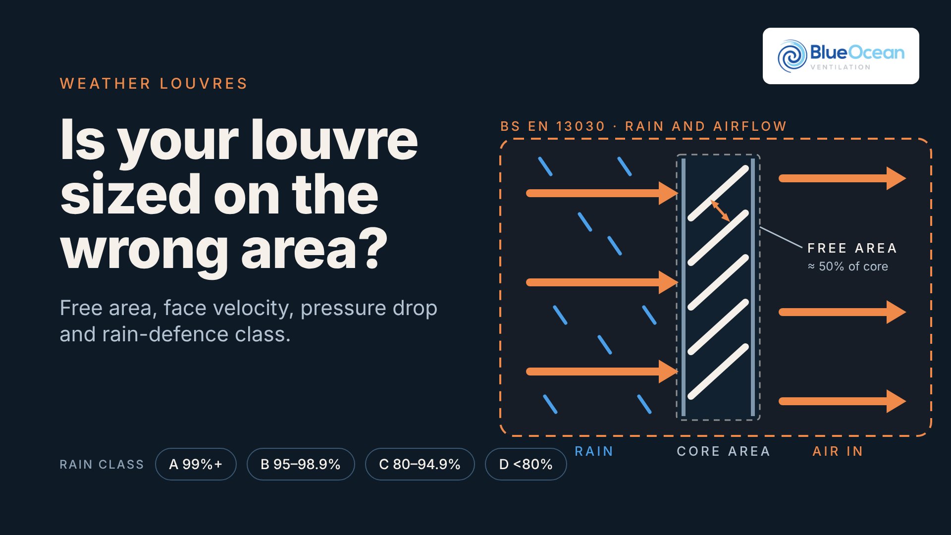
A weather louvre is usually the cheapest component on an air handling system. It is also one of the few that can flood a plant room, and it is still selected, far too often, on one number that says almost nothing about rain or airflow: percentage free area.
My point is simple. Specify louvres on tested performance to BS EN 13030: a rain-defence class at a stated velocity, plus an airflow class. Size them on a velocity whose reference area is written down. Do that and you control water ingress, fan energy and façade space in one decision.
Three areas, three velocities
Most louvre arguments on site come from people quoting different velocities for the same louvre.
Face area – the overall size, frame included. Velocity on this area is the lowest of the three.
Core area – the clear opening inside the frame with the blades removed. Colt notes this "measured free area" is now often called the core area, and says performance specifications should always state the design core velocity.
Free area – the narrowest gap between blades. Manufacturers measure it in different ways. HVC quotes about 50% for its standard single-bank range, so velocity here (often called jet or free-area velocity) is roughly double the core velocity.
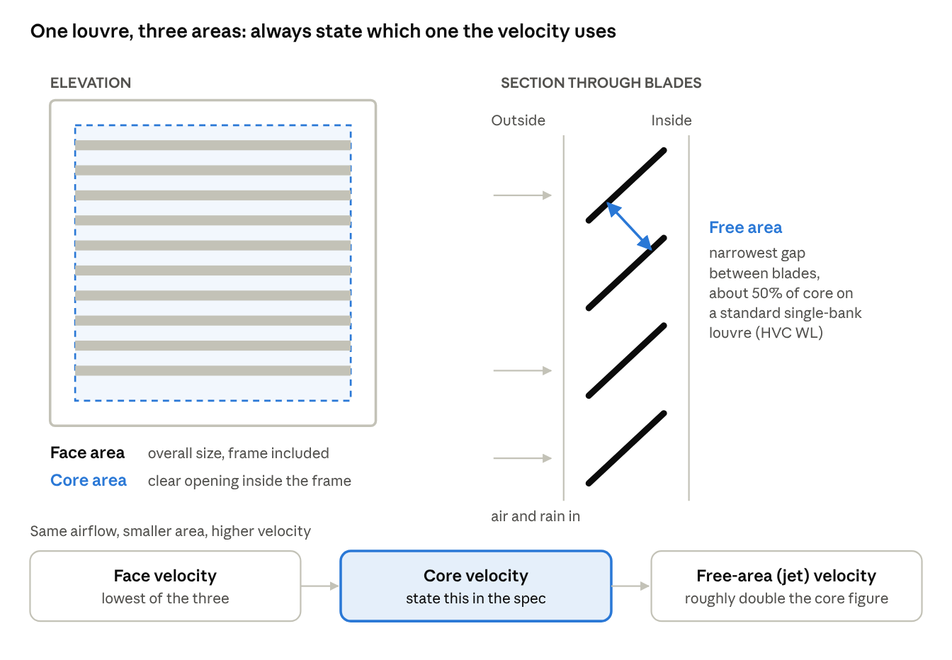
So "2.5 m/s" can describe a generously sized louvre or one running twice as hard. The first question on any louvre schedule is: velocity through which area?
Free area does not predict airflow either. HVC's own datasheet warns that two louvres with identical geometric free area can behave differently, and Colt calls free area "a wholly meaningless measure" of performance. The number that matters is the tested aerodynamic coefficient (Ce on intake, Cd on discharge): the fraction of the core area that behaves like a perfect opening.
What BS EN 13030 actually tells you
BS EN 13030:2001 tests a 1 m × 1 m louvre in a 13 m/s wind with 75 l/h of simulated rain, while air is drawn through at 0 to 3.5 m/s in 0.5 m/s steps. Each louvre gets two ratings.
Rain defence, Class A to D – A rejects 99% or more of the water, B 95–98.9%, C 80–94.9%, D under 80%.
Airflow, Class 1 to 4 – by coefficient: Class 1 is 0.4 and above, 2 is 0.3–0.399, 3 is 0.2–0.299, 4 is below 0.2.
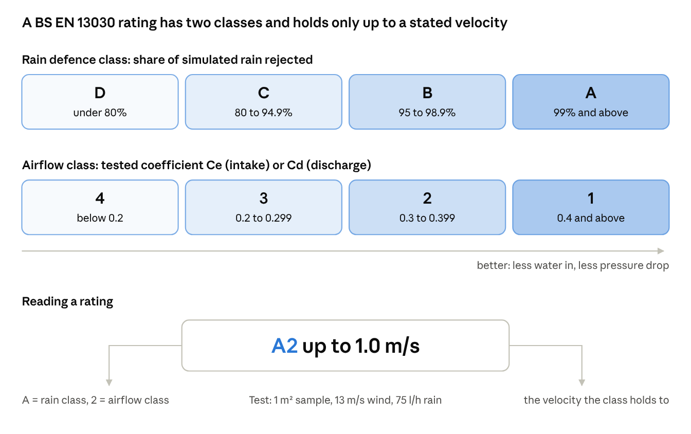
The catch is that rain class depends on velocity. Breathing Buildings gives the example of a louvre that is Class A at 0.5 m/s but Class C at 2.0 m/s. A spec that says "Class A louvre" with no velocity is incomplete; it should read, for example, "Class A2 up to 1.0 m/s".
Real products show the spread. HVC publishes its standard 75 mm louvre with drip tray as Class C up to about 1.4 m/s jet velocity and Class D above it. Its performance louvre is listed as Class A2 up to 2.5 m/s with bird mesh. Same supplier, very different water risk.
For exhaust louvres, Colt advises rating rain defence at 0 m/s: the fan-off case, when nothing is pushing rain back out.
How I apply the classes (my judgement, not a code requirement):
Class A – intakes that feed an AHU inlet or an undrained plenum directly, and openings into switchrooms, generator rooms or IT spaces.
Class B – intakes into a tanked, drained plenum with falls to an outlet.
Class C or D – exhaust discharges, visual screening, and openings into spaces that tolerate water, such as open plant decks.
Pressure drop: the square law that lands in your SFP
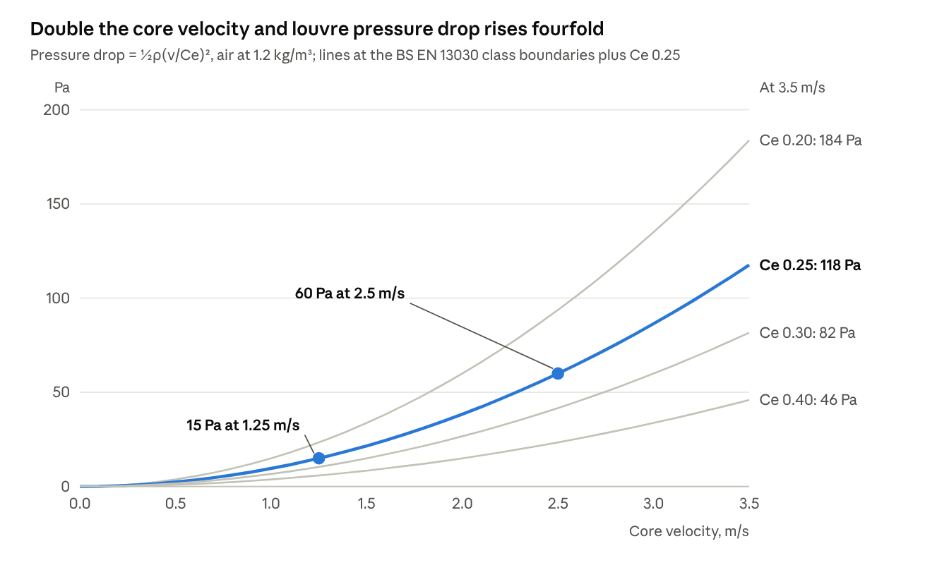
Louvre pressure drop follows the standard orifice relationship, with v the core velocity and Ce the tested coefficient:
Δp = ½ ρ (v / Ce)²
With air at 1.2 kg/m³, a Class 3 louvre with Ce of 0.25 loses about 15 Pa at 1.25 m/s. Run the same louvre at 2.5 m/s and it loses about 60 Pa. Halve the louvre and you quadruple the loss.
That loss sits inside the system specific fan power. Approved Document L Vol 2 (2026), para 5.56 and Table 5.9, caps SFP in new buildings at 1.5 W/(l·s) for most central balanced systems, 1.9 with heating only and 2.0 with heating and cooling, calculated to BS EN 16798-3 at full design load.
At an assumed overall fan efficiency of 60%, every 100 Pa of resistance costs about 0.17 W/(l·s). Two undersized louvres, intake and exhaust, each 45 Pa worse than they need to be, add 0.15 W/(l·s). That is a tenth of the 1.5 limit spent on two components at the building edge.
The commercial view
Take a 3.0 m³/s AHU with an intake and an exhaust louvre, both the same Class 3 product (Ce 0.25). The only choice is how hard to run them.
| Per system | Tight: 2.5 m/s core | Generous: 1.25 m/s core |
|---|---|---|
| Core area per louvre | 1.2 m² | 2.4 m² |
| Pressure drop per louvre | 60 Pa | 15 Pa |
| Extra fan input power | 450 W | baseline |
| SFP penalty | +0.15 W/(l·s) | baseline |
| Extra energy at 3,000 h/yr | 1,350 kWh | baseline |
| Extra cost at 24.51 p/kWh | about £330 a year | baseline |
Assumptions: 60% overall fan efficiency, 3,000 operating hours a year, and DESNZ's average non-domestic electricity price for Q2 2026 including CCL. Over a 20-year life that is roughly £6,600 at today's price, before discounting.
Capital – louvre cost rises with area, but it is a small line item. Set the quoted difference against the running cost above; the generous louvre usually wins.
Space – the real cost is façade area and the conversation with the architect. Agree louvre areas at RIBA Stage 2–3, not once elevations are frozen.
Risk – water in a filter section or switchroom costs far more than the louvre: wet media, corroded casings, tripped electrics and an insurance claim.
Maintenance – insect mesh adds resistance and blocks; bird mesh is the usual default. Give access to clean the mesh and plenum, and drain the plenum floor.
Compliance – Approved Document F Vol 2, paras 2.2–2.9, covers siting: intakes away from pollution sources, exhausts downwind of intakes where there is a prevailing wind, and no exhaust into courtyards or enclosures. A well-chosen louvre in the wrong place still fails.
How I would choose
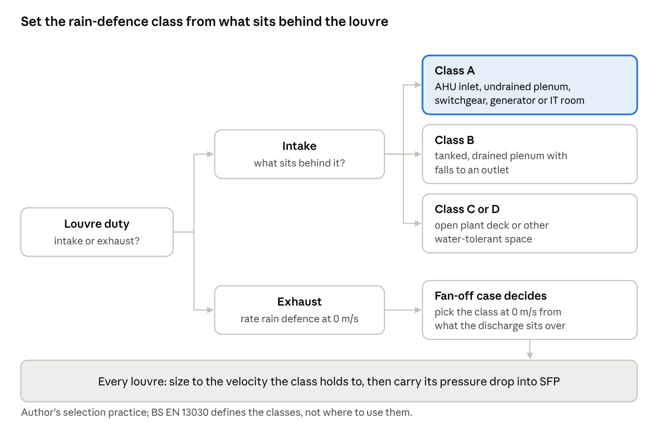
Fix the airflow and what sits behind the louvre: an AHU inlet, a drained plenum or an open plant deck.
Set the rain-defence class from that risk, at the design velocity. For exhausts, rate it at 0 m/s.
Write the velocity reference area into the spec. Core velocity, with face and free-area figures alongside.
Size from the manufacturer's tested BS EN 13030 data, not free area, and ask for the test report.
Carry the louvre pressure drop, with mesh fitted, into the SFP calculation.
Check siting against Approved Document F Section 2 and allow access for cleaning.
Over to you: what velocity do you size weather louvres to, and does your spec say which area it refers to?
References: Approved Document F Vol 2, 2021, paras 2.2–2.9 · Approved Document L Vol 2, 2026, para 5.56 and Table 5.9 · BS EN 13030:2001 · BS EN 16798-3 · HVC: What is BS EN 13030 · HVC performance louvres · HVC Series WL datasheet (Feb 2023) · Colt: Designing performance louvre systems · Breathing Buildings on BS EN 13030 · DESNZ Quarterly Energy Prices, Sept 2026