
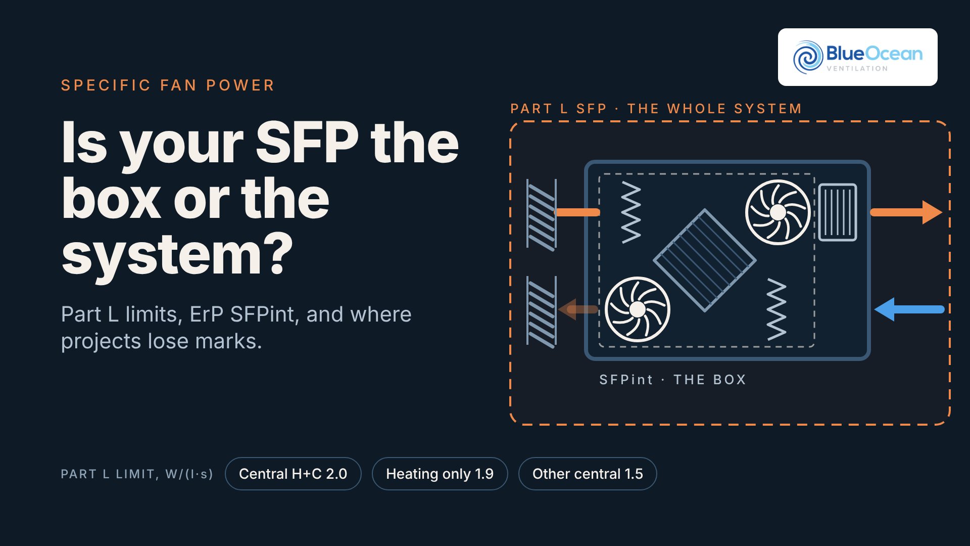
Two numbers called SFP sit on most commercial ventilation schedules, and they are not the same thing. The ErP figure on the AHU data sheet, SFPint, describes how efficiently the box moves air through its own internals with clean filters. The Part L figure is what the whole system draws from the mains, both fans, at design flow, through every metre of duct, louvre and attenuator.
Projects lose marks in the gap between the two. A unit that passes Ecodesign comfortably can still push the system over the Part L limit, or leave too little budget for the ductwork. This article sets out what each number measures, where the pressure goes, and what I check before an AHU selection is signed off.
Part L: the system number
Approved Document L Volume 2 defines SFP as the power needed to move air through the air distribution system, in W/(l·s) (Appendix A). In the 2026 edition, para 5.56 says system SFP at the design flow rate should not exceed Table 5.9, calculated to BS EN 16798-3 at full design load (BS 8850 for fan coil units).
The limits most consultants use, new buildings (existing in brackets), Table 5.9:
Central balanced, heating and cooling: 2.0 W/(l·s) (2.6)
Central balanced, heating only: 1.9 (2.2)
All other central balanced: 1.5 (2.0)
Zonal supply, fan remote from zone: 1.1 (1.4)
Local supply or extract unit, such as toilet extract: 0.3 (0.4)
Fan coil units, rating-weighted average: 0.4
For balanced systems the limit already includes heat recovery and the return filter (note 2). You may add 1.0 for a HEPA filter, 0.1 for a humidifier or dehumidifier, and 0.3 each for active chilled beams or a transpired solar collector (note 3).
The surrounding paragraphs matter as much as the table. Para 5.52 asks for SFP at 25% of design flow to be no greater than at 100%. Para 5.53 requires variable speed drives on general air distribution fans over 1,100 W. Para 5.54 calls for ductwork to DW/144 (or BS EN 1507, 12237 and 13403), and para 5.55 for AHU casings to BS EN 1886 leakage class L2.
Which edition? The 2026 edition takes effect on 24 March 2027 (24 September 2027 for higher-risk building work). Until then the 2021 edition applies, and its Table 6.9 carries the same headline limits for central balanced systems. Projects with a building notice, initial notice or full plans application in before 24 March 2027, and work started before 24 March 2028, keep transitional protection under Circular Letter 01/2026.
ErP: the box number
Ecodesign Regulation 1253/2014, retained in GB law, regulates the product, not the building. Most commercial AHUs are non-residential units (NRVUs): over 250 m³/h, unless declared for residential use only (Article 2). Annex III sets the current tier, in force since 1 January 2018:
Heat recovery: minimum dry thermal efficiency of 73%, or 68% for run-around coils.
SFPint limit, plate or wheel units: 800 + E − F W/(m³/s) at 2 m³/s and above; 1,100 + E − 300 × qnom/2 − F below that. Run-around units start at 1,300 and 1,600.
Efficiency bonus E: (ηt − 0.73) × 3,000, so better heat recovery earns more internal pressure drop.
Filter correction F: 150, 190 or 340 deducted if the medium filter, the fine filter or both are missing from the reference configuration (Annex IX).
SFPint is the internal pressure drop of the ventilation components divided by fan efficiency. It is declared for a reference configuration: casing, fans, heat recovery, a clean fine supply filter and a clean medium extract filter (Annex I, Part 2). Coils and other non-ventilation components sit outside it as Δps,add, and the external system is not in it at all.
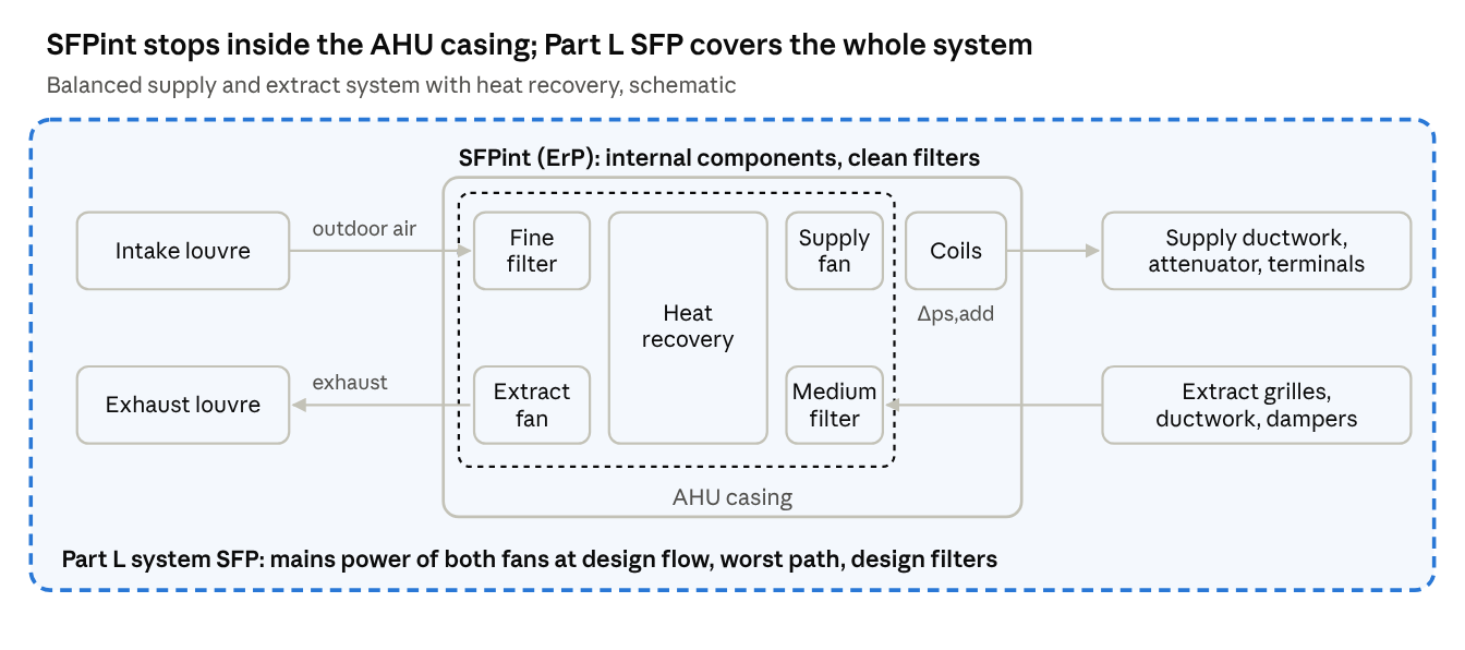
Watch the units. SFPint is in W/(m³/s); Part L is in W/(l·s). Divide by 1,000 to compare.
A worked example shows why this matters. Take a 2.5 m³/s unit with a plate exchanger at 80% dry efficiency. E = (0.80 − 0.73) × 3,000 = 210, so the limit is 800 + 210 = 1,010 W/(m³/s), about 1.0 W/(l·s). The box can legally use around half of a 2.0 Part L budget before a metre of duct is connected, with clean filters and no coils counted.
Where projects lose marks
The system SFP is total fan pressure divided by overall fan, motor and drive efficiency, summed for supply and extract. Most failures I see come from one of these:
Comparing the wrong numbers. A data sheet SFPint of 950 W/(m³/s) gets read as 0.95 W/(l·s) “for the system”. It covers the box only, with clean filters, and excludes coils.
Designing on clean filters. BS EN 16798-3 takes the design load condition with semi-dirty filters, not clean ones. AHU selections are often run at clean filter.
The index run is not the worst path. The fan must beat the worst path. Fire dampers, VAV boxes, attenuators and longer runs added late all land on it.
Louvres and attenuators sized last. Intake and discharge louvres, cross-talk attenuators and terminals are external pressure the AHU selection never saw.
Forgetting the extract side. Part L SFP is the mains power of supply and extract fans, including drives and controls, divided by the design flow.
Value-engineered casings. A smaller AHU raises face velocity and internal pressure drop. ErP Annex V requires the face velocity to be declared, so check it.
Turndown. Para 5.52 needs SFP at 25% flow no worse than at full flow. Fixed duct static pressure control on a VAV system can fail this.
The illustrative build-up below shows how quickly a typical-looking selection runs out of budget.
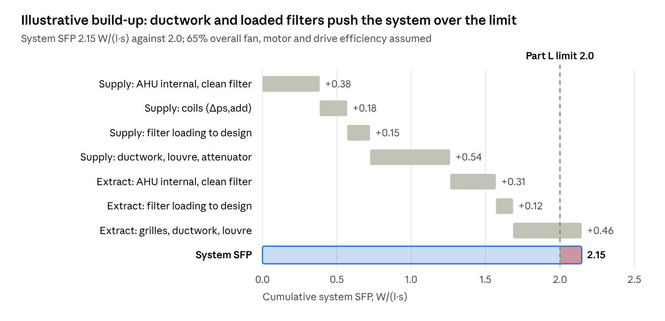
The two “AHU internal” rows are roughly what a data sheet SFPint reflects. Everything else is what the Part L check adds.
The commercial view
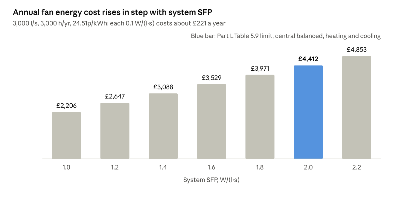
SFP is fan power per unit of air, so its cost scales directly with flow and run hours. Take an illustrative 3,000 l/s system running 3,000 hours a year. Each 0.1 W/(l·s) is 300 W, or 900 kWh a year. At the DESNZ average non-domestic electricity price of 24.51p/kWh including CCL (Q2 2026), that is about £220 a year.
The gap between a system scraping in at 2.0 and one designed to 1.5 is about £1,100 a year on that example, before any price rises. Over a 15-year AHU life that is roughly £16,500 undiscounted, which often pays for the larger casing.
Capital and space. Lower SFP usually means a bigger AHU casing, larger ducts and more louvre area. That costs plant room and riser space, so it has to be decided at Stage 2 or 3, not at tender.
Risk. A late Part L failure means reselecting plant after the structure and plant space are fixed. Fans run up at commissioning to hit design flow also raise the as-built SFP.
Maintenance. Changing filters at a lower final pressure drop saves fan energy but buys more filters. ErP Annex III already requires an alarm when the filter exceeds its maximum final pressure drop, so set that point deliberately.
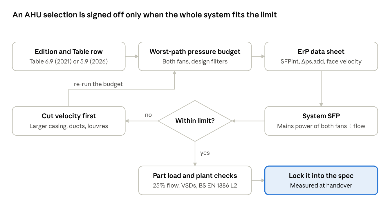
What I check before signing off
Confirm which Part L edition applies and which Table row the system falls in, plus any note 3 allowances.
Build a pressure budget on the worst path, supply and extract, with design (semi-dirty) filters, louvres, attenuators and terminals included.
Take SFPint, Δps,add and face velocity from the ErP data sheet, and convert units before comparing.
Calculate system SFP from mains power of both fans, including drives, at design flow.
If it fails, reduce velocity first: a larger casing, larger ducts or more louvre free area. Then look at fan selection.
Check SFP at 25% flow (para 5.52), VSDs over 1,100 W (5.53) and BS EN 1886 class L2 (5.55).
Write the SFP into the specification as a performance requirement, so value engineering and commissioning cannot quietly erode it.
Where does your SFP budget go first on real projects: the unit, the ductwork, or the louvres and attenuators?
References: Approved Document L Volume 2, 2026 edition, paras 5.51–5.56 and Table 5.9 (gov.uk); Approved Document L Volume 2, 2021 edition incorporating 2023 amendments, Table 6.9 (gov.uk); Future Homes and Buildings Standard circular, March 2026 (gov.uk); Commission Regulation (EU) 1253/2014, Annexes I, III, V and IX (legislation.gov.uk); BS EN 16798-3 and BS 8850; Svensk Ventilation, Recommendations on SFP definitions, rev 4.3 (Swegon); DESNZ Quarterly Energy Prices, September 2026 (gov.uk).